


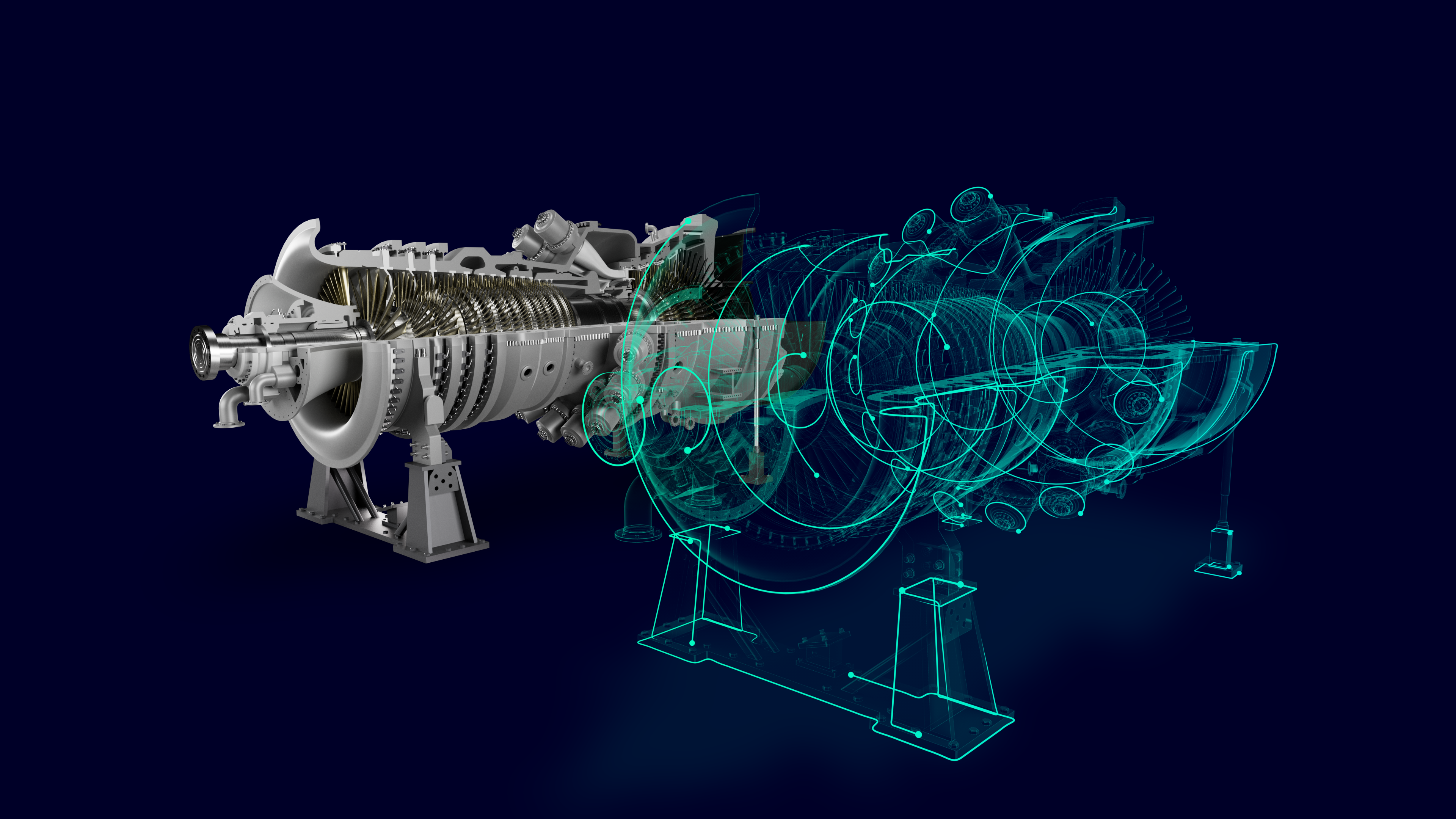
Gas turbine technology has established itself ubiquitously as a reliable and robust power generation and aviation propulsion method. The general operating principle involves sucking air in, compressing it to a higher pressure and temperature using an axial compressor, adding fuel to the compressed air in a combustor and igniting it to produce a high-temperature flow. This high temperature and pressure flow enters a turbine section, producing a rotational work output. Additional components are added to the gas turbine depending on the application. For example, a steam turbine and a generator create a combined-cycle power plant for power generation or a propelling nozzle to produce thrust for flight.
Since the creation of gas turbines, numerous advances have been made to make more powerful and efficient engines. This involved things like using incredibly advanced simulation capabilities to try and understand the highly coupled physics within the gas turbine hot gas path, as well as significant developments in materials (single crystal superalloys, thermal barrier coatings) to ensure that the metal can withstand the ever-increasing and harsh operating environments.
Coupling these engineering challenges with the current migration to green energy, a power generation gas turbine is now frequently used to support green energy sources that depend on favorable weather conditions. This results in more start-and-stops, faster loading and alternative fuels like hydrogen.
One such development in the field of computational analysis was the creation of a whole engine model (WEM). Depending on the company, this can mean a rotor dynamics model, or in the case I will speak about here, a thermo-mechanical 2D model that represents the complete gas turbine from the compressor bearing to turbine bearings.
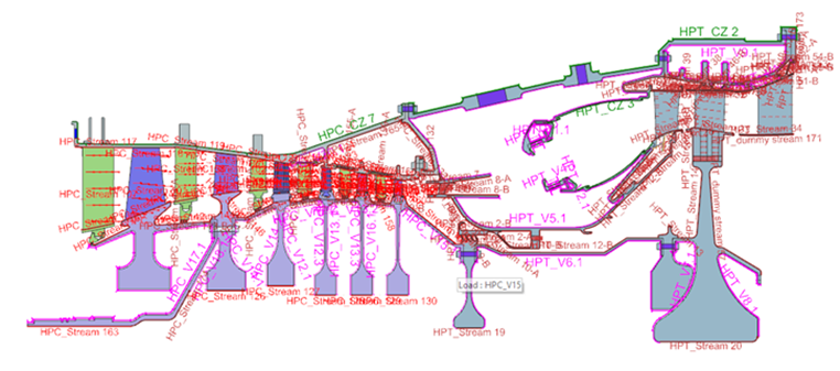
The whole engine model (WEM) is an approach taken within the power generation and aviation industry to model a complete gas turbine through a wide range of operational scenarios. Operational scenarios are defined as the sequence of starting, loading, baseload or cruising operation and de-loading to rundown and rotor barring until the engine is cooled. The thermal state of the engine, especially in power generation gas turbines, dictates when a restart can occur, as rubbing of stationary and non-stationary components can otherwise occur, causing damage to the engine and the subsequent performance.
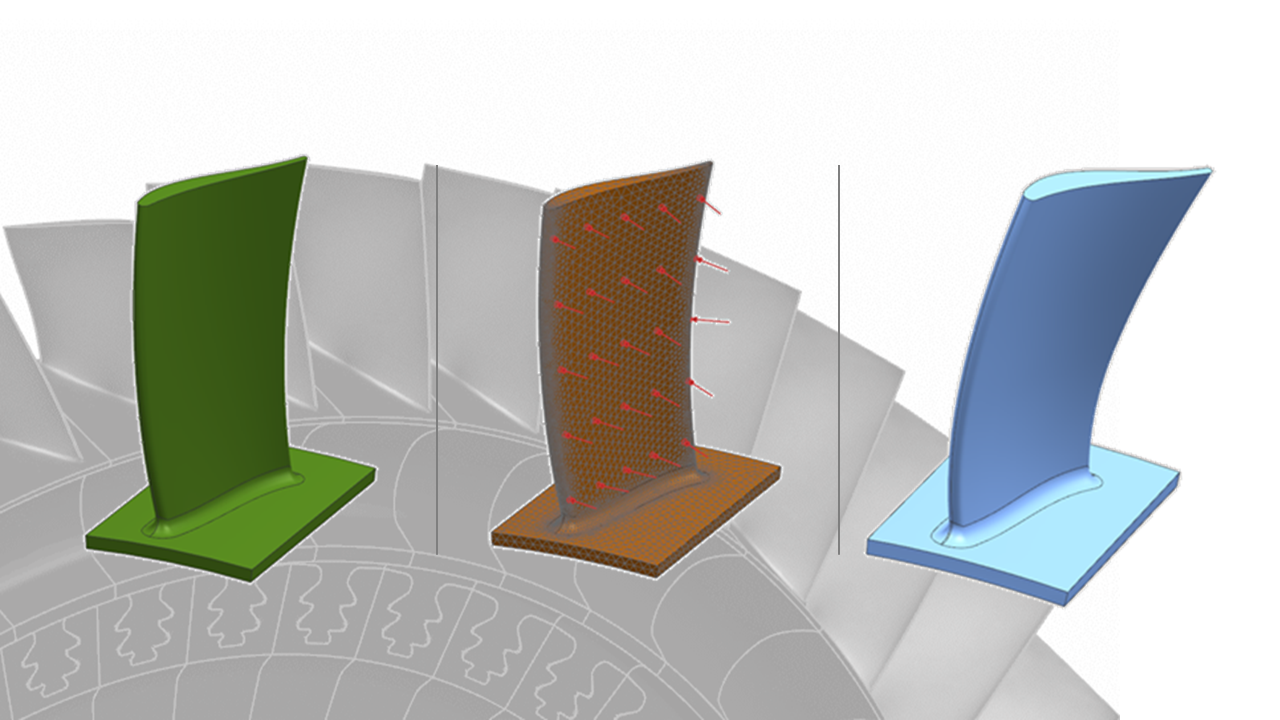
The whole engine model is created by taking the 3D geometry and mapping it onto a 2D plane. Due to the axisymmetric nature of gas turbines, the model is divided into axisymmetric and non-axisymmetric parts. Non-axisymmetric parts are assigned a thickness to account for the differences around the circumference, such as flanges, air extraction ports, blades, and vanes. This typically requires close collaboration between the thermo-mechanical engineer and design engineers of the different components.
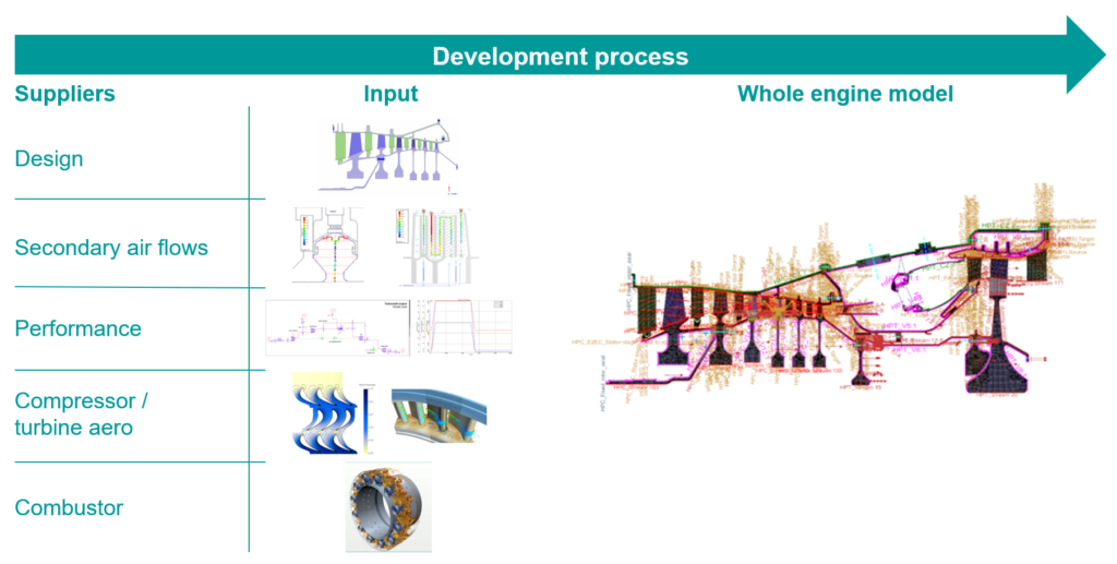
Due to the nature of the model, the lead engineer needs to coordinate with all departments to collect input for the model:
- Geometry and materials of the engine �C design department
- Cooling flows networks �C secondary air flow department
- Operation/mission cycle �C performance department
- Aerodynamic loads �C turbine and compressor departments
- Cooling flow network and heat transfer coefficients �C combustor department
An integral part of the whole engine model are the turbomachinery-specific boundary conditions that model the specific behaviors of the convecting fluid. These boundary conditions can be linked together, creating a 1D flow network that accounts for the flow throughout the engine. The boundary condition inputs allow for both static and rotational frames of reference, while a company��s in-house expertise, which has been developed over the years, can be incorporated into the heat transfer correlation expressions.
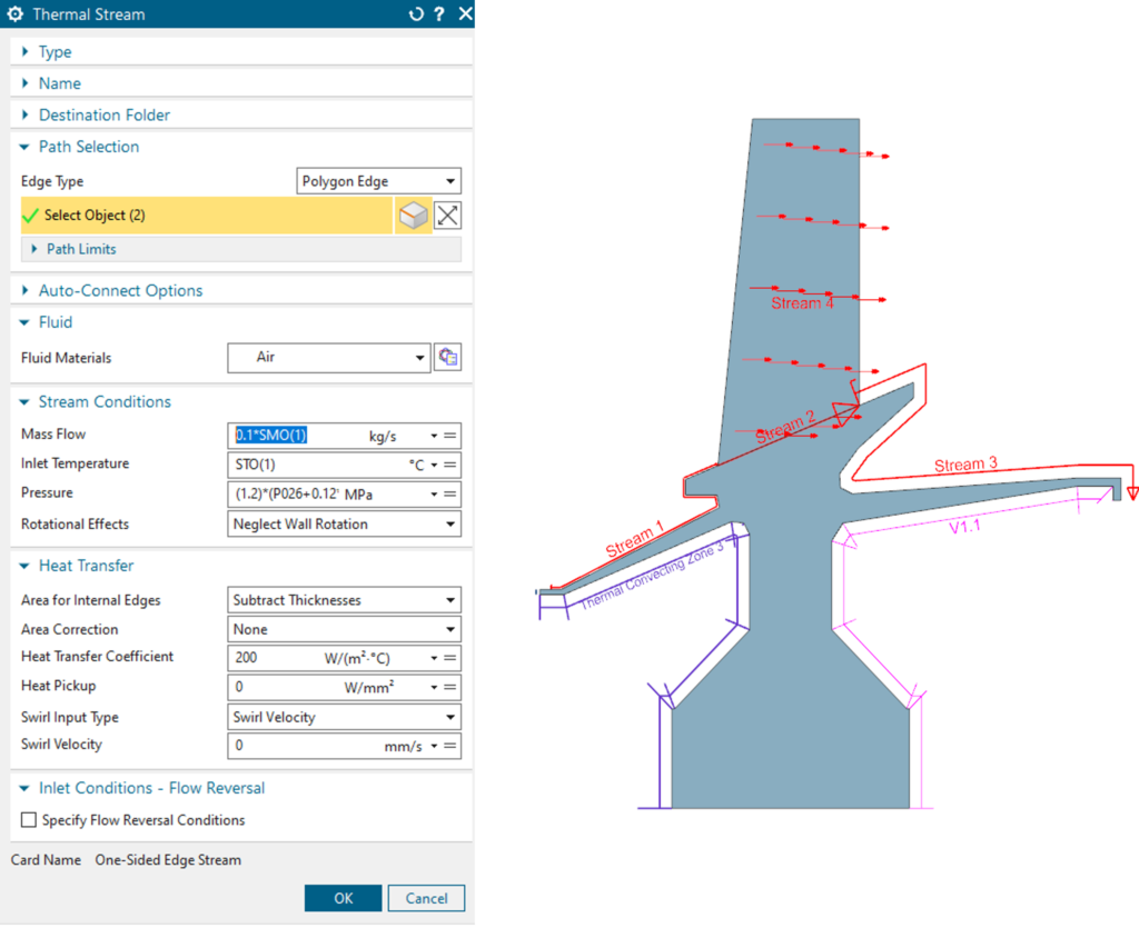
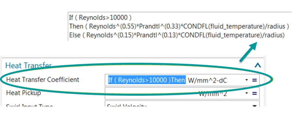
As the main physical parameters of the convecting fluid (pressure, flow rate, temperature) evolve over the engine operation, it is pertinent to account for the changing physics involved �C below a certain rotational speed, the flow is not convected through the engine, and this can lead to a different heat transfer process. The whole engine modeling process can account for this in the boundary conditions in two ways:
- Incorporation of if/then statements in boundary condition input fields
- Links to the key parameters from the mission/operational cycle that evolve over time
The culmination of all the boundary conditions and other inputs results in the whole engine model becoming a master model or digital twin of how the complete engine behaves and performs under a range of operational conditions �C the results one attains are not just steady state results of one time point, but transient results over the complete mission cycle of the gas turbine engine.
Two key results over the transient cycle are the metal temperatures of the gas turbine components and the clearances �C the gaps between the rotating and stationary components.
Gas turbine engineers can understand how the different components in a gas turbine engine interact with each other over range of operational modes, whatever that specific operational cycle is �C a normal start up and loading gradient, all the way through to a hot restart or a faster loading cycle. In this regard, the metal temperatures will have a particular thermal behavior which can be used to understand things like mechanical integrity life, or clearance evolution.
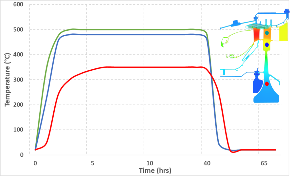
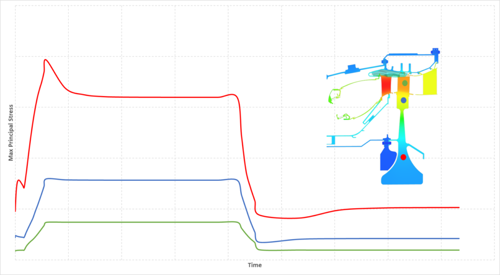
This temperature graph (created for illustrative purposes and is only indicative of a real gas turbine engine) illustrates how the temperature in one blade and disc evolves over a mission cycle. The differences in temperatures are a function of the local heat transfer coefficients as well as the mass distribution. This leads to thermally induced stresses in the metals that can have an impact on metal lifetime, especially significant in mechanically loaded areas like the firtree connections of a blade and rotor. The following graph is an indication of the differences in stresses that can be present in the rotor disc as a result of the temperature differences.
A significant advantage of running a 2D whole engine model is capturing a complete gas turbine��s thermal behavior over any number of potential operational scenarios. Due to both the axisymmetric and non-axisymmetric nature of the geometry, 3D models are expensive computationally and typically slow �C utilizing the thermal results of a WEM, the structural team has transient inputs that can be used to identify the mechanical behavior of the various individual components and parts of a gas turbine. Lifetime assessments, 3D deflections and ovality are all things that can be derived from the 3D models and subsequently correlated to the type of operation the gas turbine undergoes.
This additional information on the 3D mechanical movements can then be shared with the clearance team enabling a complete picture of the 2D and 3D clearances �C critical information to understand the performance of the gas turbine. Again, this is possible with any range of operational cycles, not just the standard run-up to baseload and shutdown, or in the case of an aero engine the standard take-off, cruise and land cycle.
In the same way that an original equipment manufacturer (OEM) wishes to understand the thermal behavior of the engine, a gap or clearance evolution is also highly desired as it directly impacts the performance of the engine as well as the structural integrity and safe operation of the gas turbine. Simulating the steady state condition of the engine allows one to understand the steady state performance. However, to understand whether rubbing will occur, when it is reasonable to restart a hot engine, etcetera, one needs to simulate the transient start-and-stop of an engine under different conditions.
The following graph is a typical example of how the clearances of one blade may evolve over an operational cycle. An arbitrary cold build clearance is chosen (the gap that exists at the start), and with the application of mechanical and thermal loads we first see the gap between the parts opening and then subsequently closing to a steady state value as the engine reaches a thermal steady-state condition.
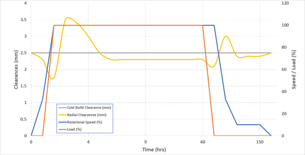
Similarly, at cool down, the gap initially closes more than the steady state due to the cooling of the external casing and then opens again with the reduction of the speed of the engine (no more rotational/mechanical load).
This example is only representative of one blade. The clearance engineer would have to carry out this analysis for each stage to determine the axisymmetric clearance picture of the engine. Subsequently, a complete picture of the clearances can be created by adding in the non-axisymmetric effects like ovality, calculated from a 3D mechanical model, and the manufacturing tolerances and uncertainties. With this information, the balance between risk mitigation and maximum engine performance can be achieved.
In summary, whole engine modeling allows you to understand the transient metal temperatures and clearances within your gas turbine engine over a wide range of operational scenarios. This master model approach enables a company to understand how components interact with each other, optimize the overall performance of a gas turbine and mitigate risks of failure and rubbing while providing mechanical integrity departments with valuable inputs for lifetime assessment. This leads you to a higher-performing engine that functions reliably for longer under more adverse operational conditions.
You might also be interested in��
Webinar
Improving aircraft engine thermo-mechanical performance
Webinar
Speed up the hot to cold blade conversion process
Blog
Thermal fatigue: some hot features in Simcenter 3D Durability